

Ausumgaard Biogas Walking Floor
References
Ausumgaard Biogas
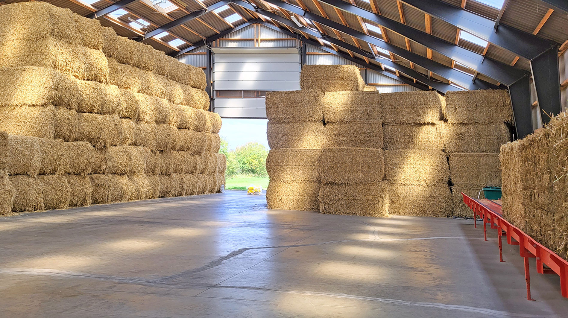
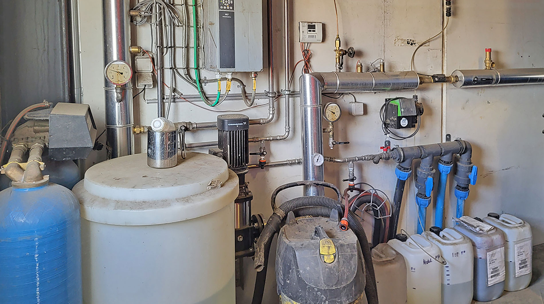
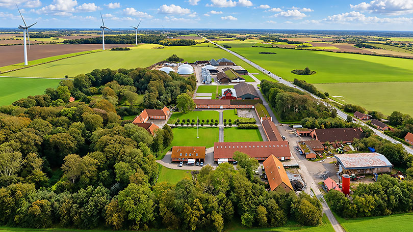
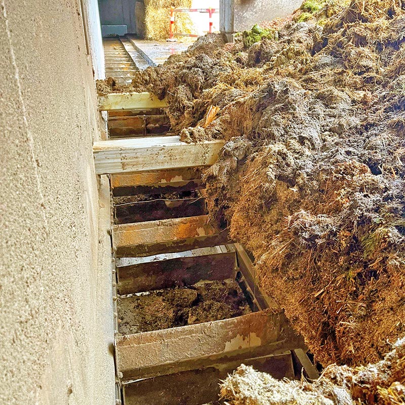
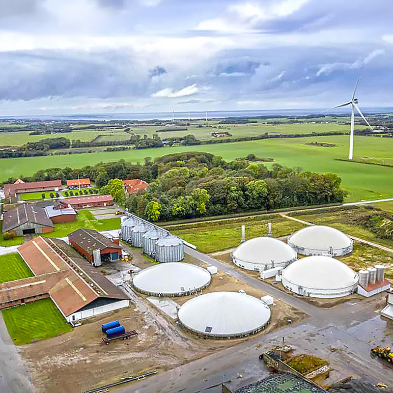
At Ausumgaard Biogas near Hjerm, Linka Energy has supplied and commissioned a heavy-duty Walking Floor solution for the automatic handling and feeding of manure fibres to the biogas plant.
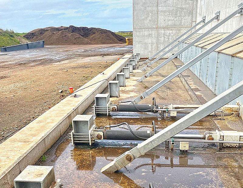
Ausumgaard handles approximately 200,000 tonnes of biomass annually, and with the biogas plant operating continuously, reliable feedstock supply is essential.
Manure fibres are a heavy and demanding material to handle, requiring a solution that ensures efficient and reliable feeding.
The investment in the Walking Floor system was also intended to reduce manual handling, save time and minimise the risk of operational downtime – an important factor for a biogas plant operating 24 hours a day, 365 days a year.
Linka® Walking Floor-scope of supply
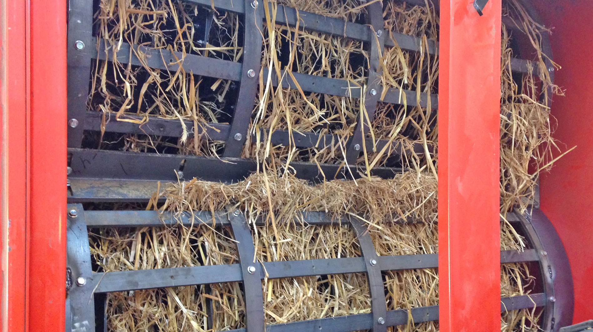
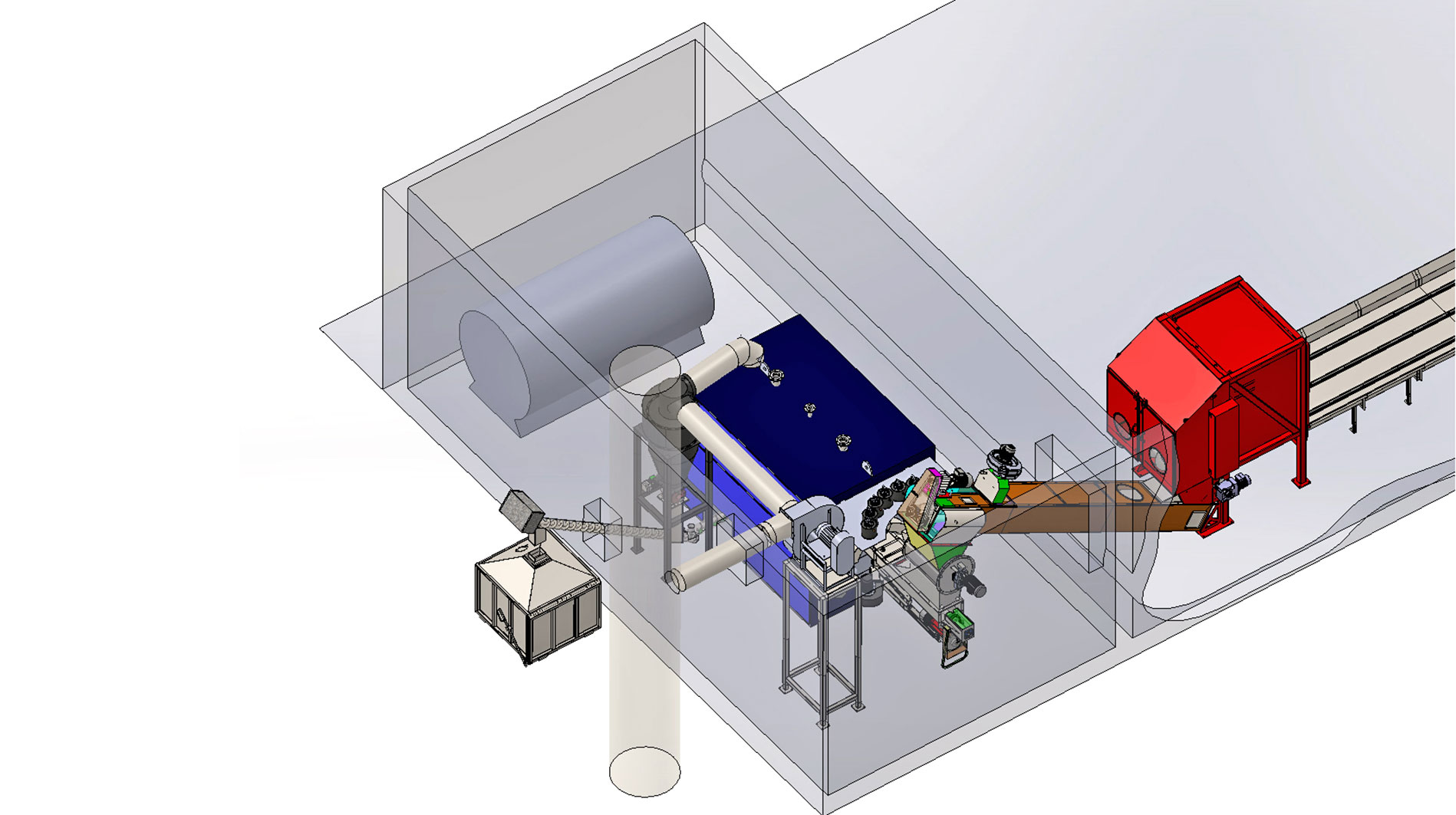
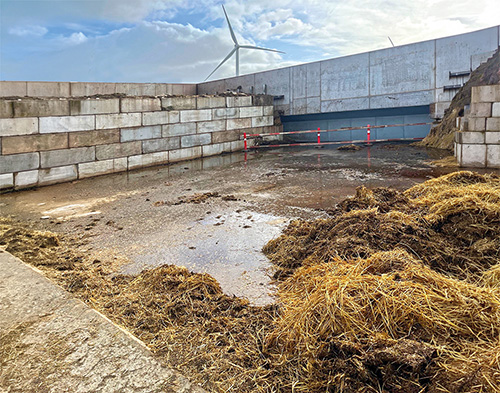
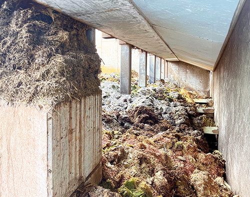
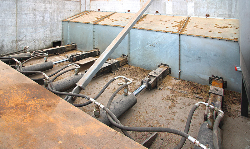
The Walking Floor system is integrated into Ausumgaards drive-in storage bays and consists of hydraulically driven scrapers that move the biomass fibres towards a recessed transverse chain conveyor. From here, the material is conveyed onwards through the existing feeding system.
The system comprises 12 heavy-duty scraper arms and 12 hydraulic cylinders powered by two hydraulic power units, together with 180 m² of Hardox floor plates and a reinforced steel structure. Linka’s scope of supply also includes control and programming, mechanical installation, start-up and commissioning, as well as training of the operating personnel.
10 mm Hardox plates are installed beneath the scrapers to protect the concrete floor against wear while providing a robust foundation for anchoring the scraper system’s reaction supports. The structure is further reinforced with HEB sections.
Designed for Biomass (deep litter, agricultural residues, straw, grass, etc.)
The system is designed for material with a density of up to 600 kg/m³ and a storage height of up to 4 metres. The hydraulic system provides a discharge capacity of up to 100 m³/hour.
The structure is also designed to allow a wheel loader weighing more than 30 tonnes to drive over the scrapers, provided that the machine is not turned or pivoted while positioned on top of them. This enables efficient loading directly into the drive-in storage bays.
Project facts
Solution: Linka® Heavy-Duty Walking Floor
Material: Biomass (deep litter, agricultural residues, straw, grass, etc.)
Material: Biomass (deep litter, agricultural residues, straw, grass, etc.)
Capacity: Up to 100 m³/hour
Material density: Up to 600 kg/m³
Storage height: Up to 4 m
Scraper system: 12 hydraulically driven scrapers
Hardox floor: 180 m² / 10 mm
Buffer capacity: Approx. 1.5 days of operation
Reliable feedstock supply around the clock
The Walking Floor system provides buffer capacity equivalent to approximately 1.5 days of operation, reducing the need for continuous manual handling and providing greater flexibility in day-to-day operation.
The solution was developed in close collaboration between Ausumgaard and Linka Energy, based on the characteristics of the manure fibres, the required capacity and the operating conditions.
The result is a robust and reliable system for handling manure fibres and the large volumes of biomass used in Ausumgaards biogas production.
Specifications

Want to know more about this project?


Nature Energy Kværs
References
Nature Energy Kværs A/S
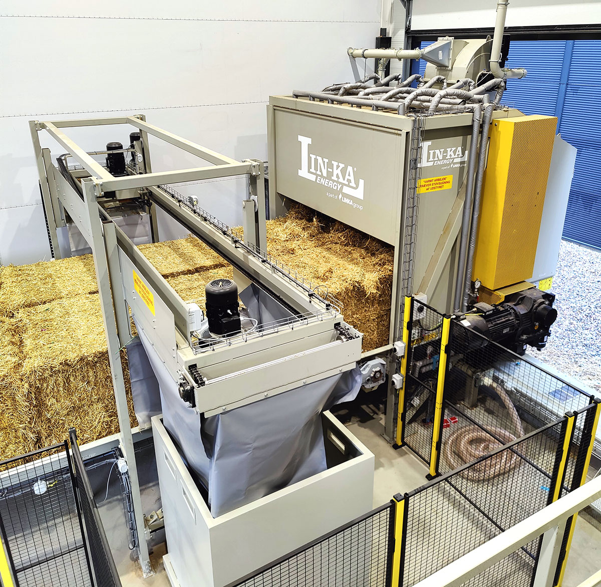
Linka® and EUROmilling’s Straw Handling System optimizes biogas production.
Nature Energy’s new biogas plant in Kværs is yet another innovative approach to green energy. Using advanced technology, it transforms organic waste from farmers, industry, and citizens into CO2-neutral biogas.
The biogas is produced through a process where bacteria at approximately 50°C convert biomass into biogas and liquid fertilizer.
After purification, the biogas can be distributed to various sectors, potentially replacing fossil fuels in transport, industry, and heating.
This case highlights Linka Energy and EUROmilling’s complete straw handling system for Nature Energy Kværs. The system includes a thermal and mechanical straw treatment plant that fully breaks down the straw, which is then utilized in the next stage of the biogas plant for biogas production.
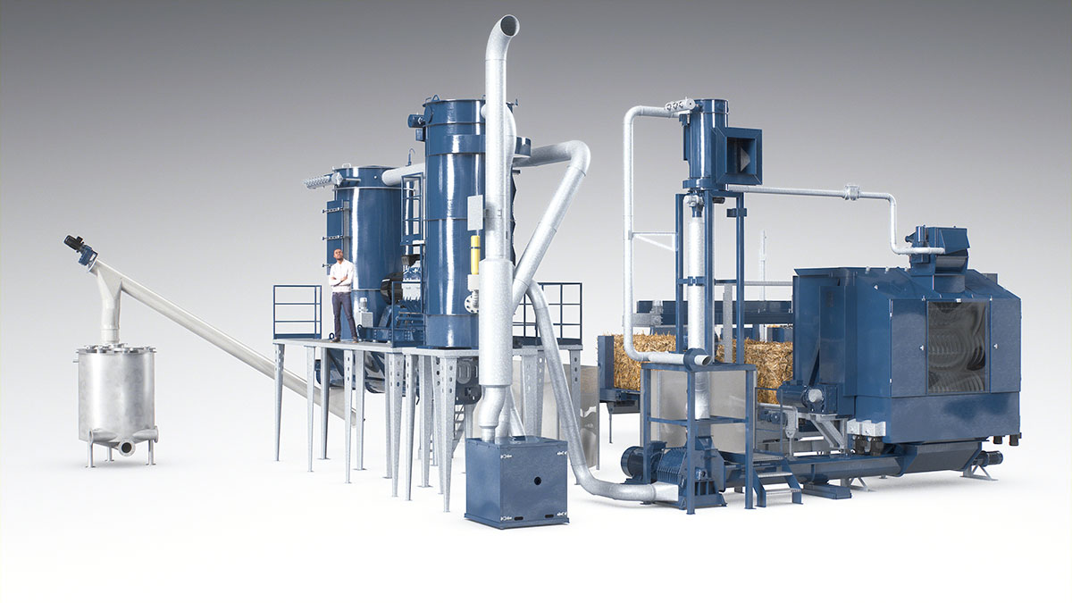
The complete plant.
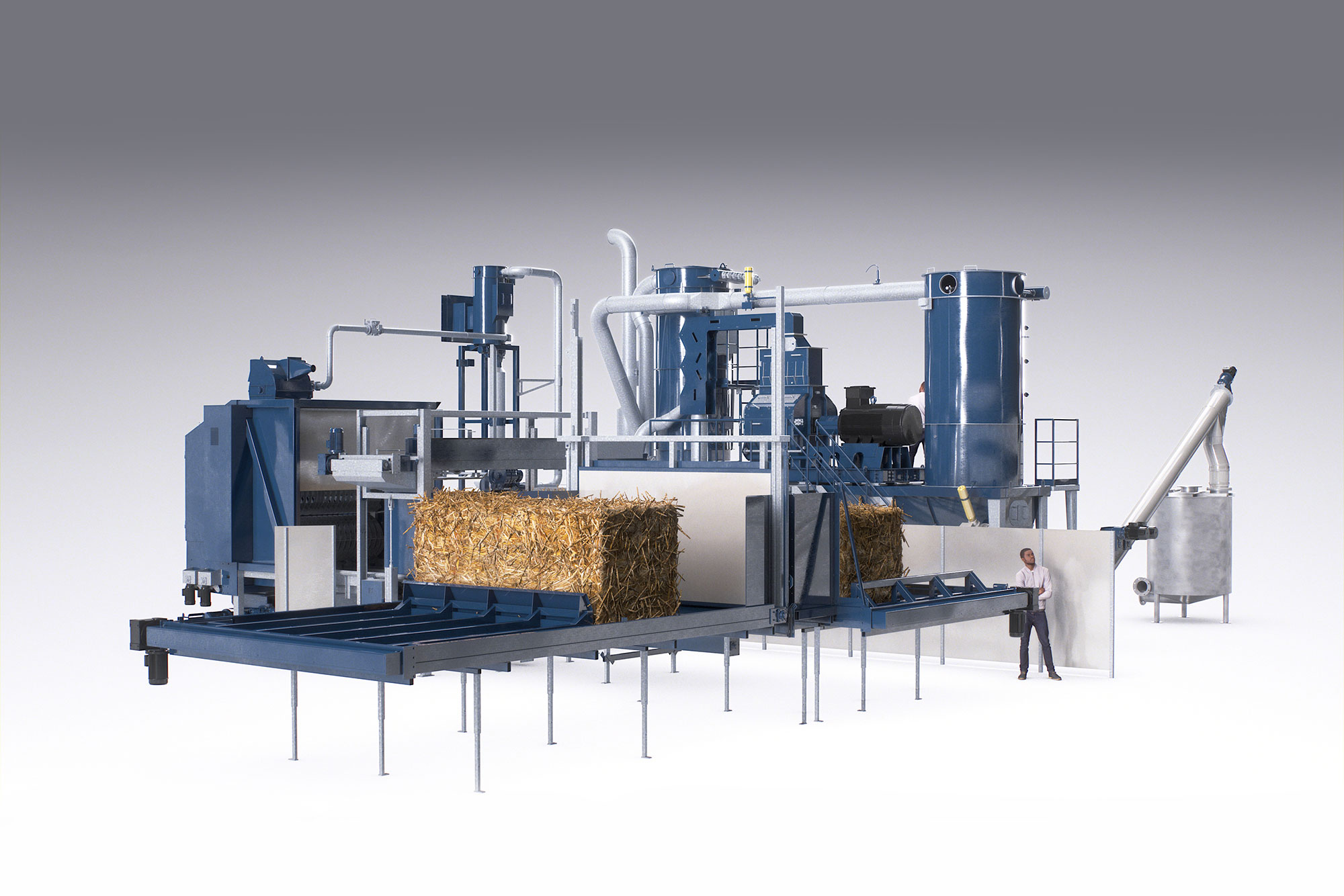
Linka® Straw Handling System.
The plant is equipped with a Linka® Straw Handling System designed to manage straw bales in midi-big and Heston bale sizes. The entire process begins at the straw storage area, where the straw crane delivers a bale to a metal detector. The detector scans the bale, and the crane either moves it to the straw conveyor or directs it to a rejection area if metal is detected.
Straw Crane.
An overhead straw crane is a crucial tool for handling straw bales in storage facilities, designed to efficiently transport, lift, and position straw bales. The installed overhead straw crane automatically places the bales on the straw conveyor and can handle up to 4 tons of straw per hour.
The crane is delivered with a local control panel and operates as a PLC-controlled unit with a user interface for both crane operation and system information display. The crane control is integrated into the SCADA system.
Safety features ensure the crane operates within secure parameters. The crane is linked to door and gate safety systems in the work area. If a door or gate is opened, all crane movements, except the grab function, are halted to prevent the accidental dropping of a straw bale.
When the system requests straw, the straw crane receives a signal to fetch a straw bale.
Pusher Table (Straw Table).
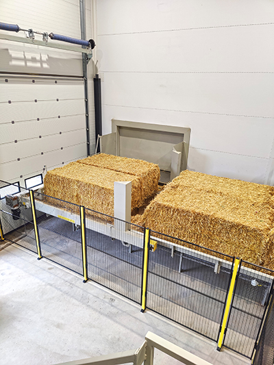
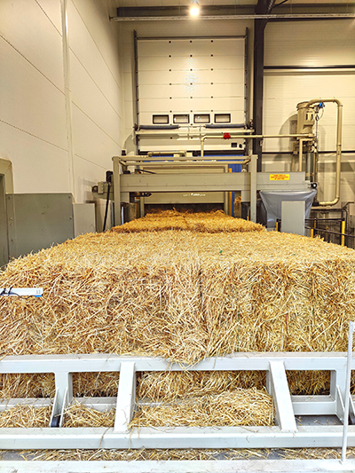
The pusher table, or straw table, is a Linka® TWIN model. This means two bales are positioned side by side along the entire length of the table, from the rear end to the shredder.
Straw bales are placed individually on the first pusher table before being moved through the fire damper and onto the next pusher table. Once two bales are positioned on the pusher table, they are pushed onto the straw table, which transports them to the string remover.
String remover
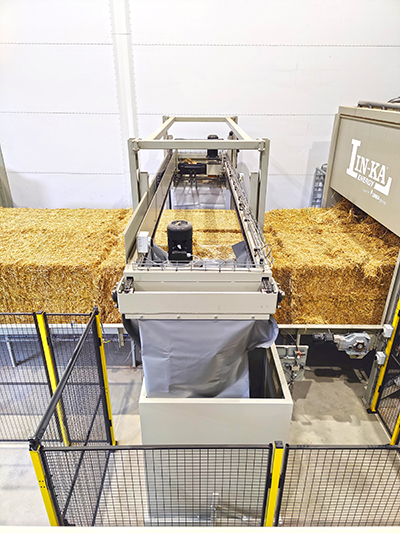
Before the straw bales enter the shredder, the strings must be removed. This process is performed automatically by a Linka® String Remover, specifically designed to prevent strings from tangling around the shredder drums.
The string remover uses photocells to position the bales accurately. The strings are then cut from underneath the bale and pulled off from above. The removed strings are wound up and separated from the straw. They are collected in a big bag, container, bucket, or a similar receptacle.
When a straw bale has had its strings removed, it continues forward towards the shredder. The photocell, now no longer interrupted, sends a signal to the straw crane to retrieve new straw bales. After the string remover, the straw shredder starts up upon receiving a signal from the straw mill.
Straw Shredder.
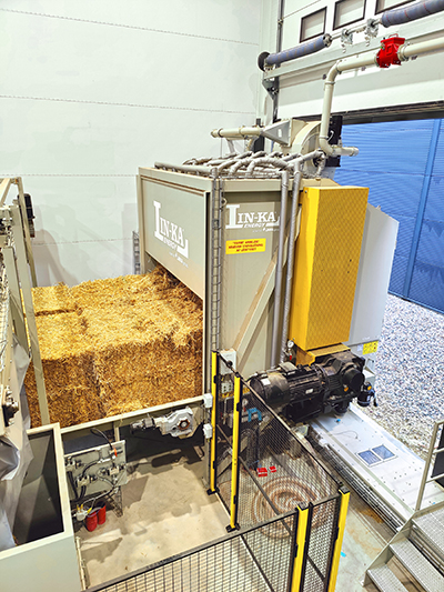
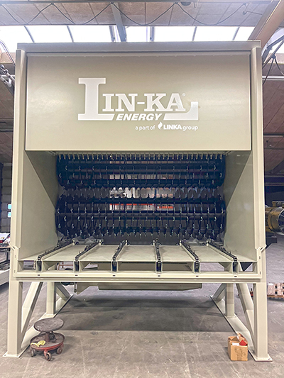
The straw shredder is a Linka® TWIN model 123, meaning two bales are positioned side by side as they enter the shredder. Inside, the straw is shredded by three drums that both cut and separate the straw fibers before they fall into the collection bin. The drums operate at low speed, which reduces energy consumption and lowers the risk of sparking.
The drums operate at low speed, which reduces energy consumption and lowers the risk of sparking. When the hammer mill ”calls” for fuel, the shredding procedure begins. This means the shredder starts by ”cutting” the two straw bales positioned inside the shredder. Here, the straw is lifted by the shredder’s drums and falls into a trough on the opposite side.
At the bottom of the trough in the shredder, two augers, one right-hand threaded and one left-hand threaded, move the shredded straw to a common, centralized outlet at the center of the shredder. From there, a double auger conveyor transports the shredded straw to the pre-mill.
EUROmilling Grinding System
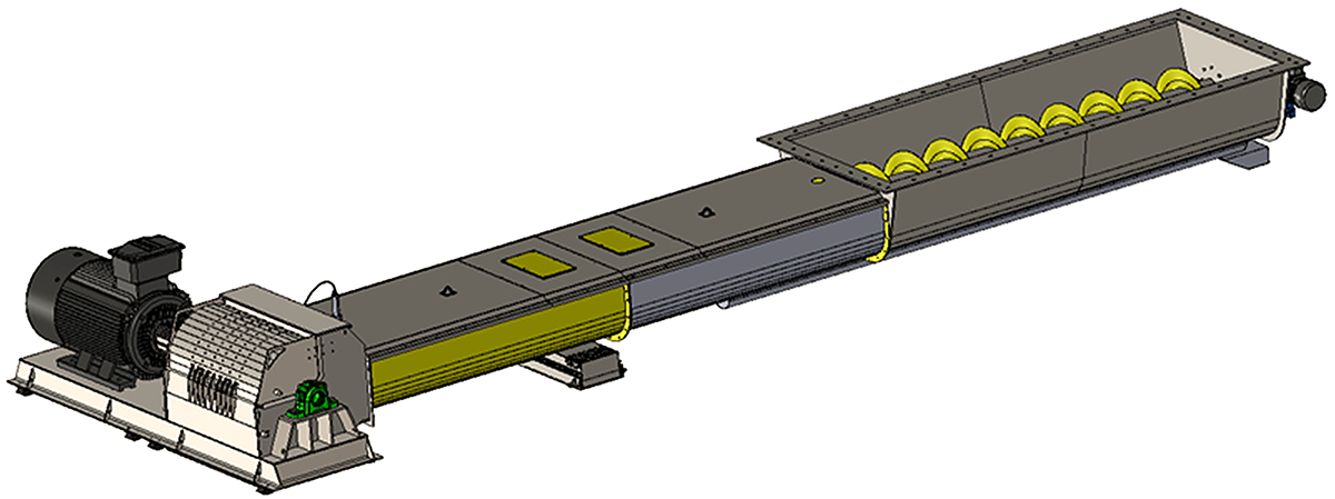
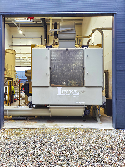
The system consists of an EUROmilling grinding setup that handles the shredded straw and includes a pre-mill, a hammer mill, and a pre-mixer.
- Pre-grinder: Prepares the straw for fine grinding;
- Hammer mill: Ensures the straw reaches the desired fine particle size;
- Pre-mixer: Homogenizes the straw for optimal biogas production.
From the shredder, the shredded straw is transported via a double auger conveyor to the pre-mill.
Hammer Mill for Straw Grinding.
The hammer mill, is a filling, grinding, and mechanical transport system that integrates all functions related to the grinding process and the mechanical transport of the finished ground straw.
Grinding occurs between hardened, loosely suspended hammers and grinding components, with wear-resistant components at the top of the grinding chamber optimizing the grinding process. These components prevent unnecessary rotation of the shredded straw, thereby increasing grinding efficiency by reducing energy consumption, minimizing wear on screens, limiting heat generation, and shortening residence time in the grinding chamber.
The grinding fineness and particle size distribution of the product are determined by the type and size of the welds.
Complete with integrated motor platform on vibration dampening kit the system includes a safety switch for the top cover, as well as a service and cleaning hatch.
The bottom outlet is equipped with an air vacuum from the fan, which draws the finished ground material through the screen, increasing capacity and cooling during the grinding process.
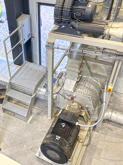
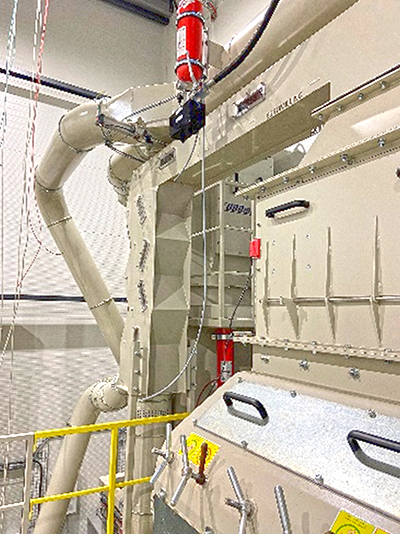
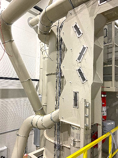
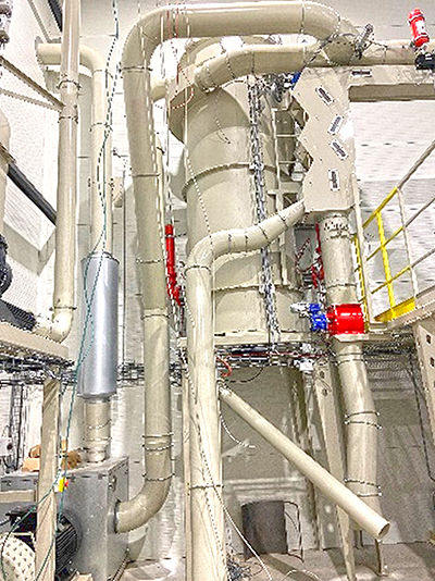
Hammer Mill, Grinding Process.
The hammer mill, type EUBL, is an efficient grinding solution that integrates metal and stone separation, air filter, fan, and a lower hopper with an extraction auger for dust-free operation. Grinding occurs between loosely suspended hardened hammers and durable, replaceable concave components at the top of the grinding chamber. The mill is reversible, which extends service intervals and optimizes energy consumption by preventing unnecessary rotation.
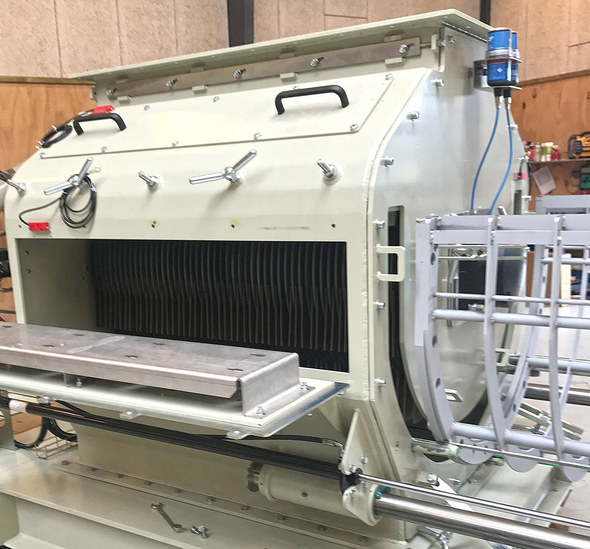
The hydraulically operated screen drawer allows for quick screen replacement, which determines the grinding fineness and particle size distribution. A vacuum fan is connected to increase capacity and cool the product during the grinding process. The mill is controlled by a variable frequency drive with a common mode filter and is equipped with vibration dampeners.
The rotor is fitted with insert-hardened hammers arranged in multiple rows to ensure consistent grinding. The magnetic separator removes heavy particles, while the air separator ensures high separation of stones and metal before the inlet. Sorted-out elements are pneumatically conveyed to a collection point in a Bigbag or container via the valve. Air intake occurs through a suction pipe, which continuously transports the material to the inlet and distributes it evenly with adjustable damper plates.
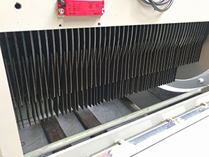 Filter.
The self-cleaning nozzle filter, Teflon-coated and anti-static, with round filter bags ensures a dust-free installation. During operation, it is self-cleaning using air pressure across multiple sections, and the cleaning process is managed by a filter control panel.
Pre-mixer.
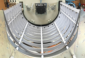 The pre-mixer is a vessel that ensures uniformity in the finished ground or shredded straw, optimizing it for the fermentation and digestion processes to achieve optimal biogas production.
From the hammer mill, the finished ground or shredded straw is transported via an auger conveyor to the pre-mixer. Here, the fermentation and digestion process begins, breaking down the straw into organic materials by microorganisms under anaerobic (oxygen-free) conditions.
Under anaerobic conditions, microorganisms decompose the organic materials into biogas through a fermentation and digestion process, producing biogas consisting of methane (CH₄) and carbon dioxide (CO₂), which is crucial for the production of methane and other gas forms. The result of methane production largely depends on the particle size of the shredded straw and its moisture content.
Control and Monitoring System.
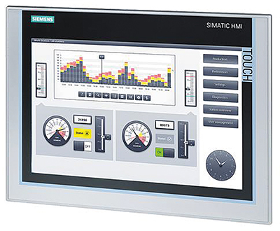 A complete control and monitoring system for the operation of the entire facility, managed from a separate control panel via the main panel. The control and monitoring system oversees, optimizes, and protects the operation, ensuring efficiency, safety, data collection, and remote control.
The control and monitoring system is based on PLC control, ensuring a controlled and logical feeding of straw bales and the hammer mill based on agreed time/signal inputs. All values and signals can be
accessed via the interface/data block in the mill monitoring PLC, either via Profinet or Profibus, according to agreed specifications. All interfaces to external control systems, such as Modbus, Profibus, Profinet TCP/IP protocols, etc., are defined in collaboration with the customer.
Electrical Installations.
Complete electrical installations, including cable ladders, cables, and other supports, for the operation of the entire facility, controlled from a separate control panel via the main panel. Complete electrical installation from the main panel to the central dust extraction system.
Central Dust Extraction System.
The central dust extraction system, wall-mounted, ATEX Zone 20, self-cleaning, and automatic (compressed air), is designed with a powerful vacuum system to collect large particles such as straw, sand, and stones.
The central unit is positioned high in the mill room and connects to a fixed piping system with suction points in both the mill room and the ”straw reception area.”
There are wall-mounted hose reel units with electric activation, extendable with a hose extension, and a vacuum pipe with a suction head.
In the straw reception area, the hose reel is mounted on a swivel arm for easier vacuuming. The collected material is automatically conveyed into the straw line during the mill operation. When the hammer mill is not in operation, the dust is transferred to a container.
Specifications
Want to know more about this project?
SAFETY ABOVE ALL.
The plant at Kværs is safeguarded against fire and explosion risks from storage to the final process. B Fire-Safe Transfer of Big Bales from Storage to the Grinding Room. The purpose of the system is to ensure that a fire in the grinding room cannot spread to the straw storage area.
Fire protection is designed and constructed in accordance with ”BS60,” ensuring only a ”free opening” between the storage and the grinding room during the transfer process. The straw feeding system is part of an integrated control function between the ”straw bale overhead crane” and the ”straw shredder.” The feeding system operates exclusively by hydraulic functions, with the oil pump station located in the grinding room.
Operational Principle:
- The straw bale is placed on the ”receiving bed” in the feeding unit.
- The ”fire door” between the straw storage and the grinding room opens.
- The straw bale is transferred from the ”receiving bed” to the ”mid-position” in the grinding room.
- The fire damper closes.
- The straw bale is transferred from the ”mid-position” to the straw push table.
All functions and operations are only performed if all other functional and safety requirements are met.
Fire Extinguishing.
A sprinkler system is installed above the straw shredder, which activates at a temperature above 50°C.
The shredder is equipped with two fire suppression systems:
- A temperature-controlled system that opens a solenoid valve.
- A mechanical system with fusible links and a pressurized container, which also operates in case of a power failure.
When the sprinkler system is activated, it is triggered either by a PT100 sensor (electronic) or fusible links (mechanical). This dual system ensures that the plant still operates during a power failure.
Activation of the sprinkler system impacts a flow switch, which also triggers an alarm. Both systems stop the plant and send an alarm.
In general, ATEX-certified components are used, including rotary valves where fine dust occurs.
Nextech: Fire Protection/Spark Extinguishing System
Spark detection and extinguishing systems are specialized fire protection solutions that detect and neutralize ignition sources such as sparks and glowing particles to prevent fire or explosion. Upon detection, a fine mist of water is released under high pressure from extinguishing nozzles within milliseconds, removing the thermal energy of the ignition source. The system can be adapted with other extinguishing agents as needed.
These systems only protect installed areas and detect infrared radiation. Compliance with fire and explosion safety regulations is required. GreCons systems are certified by VdS (E 8850001) and FM (NC 5AO.AY, OT 1A2.AY).
Note that interfaces to external control systems, such as Modbus, Profibus, and TCP/IP protocols (Profinet), are not described here. These specifications can be tailored and specified in collaboration with the customer as needed.
In Brief.
The plant at Nature Energy in Kværs is an extremely efficient facility with low operating costs compared to competing technologies. The StB plant from Linka Energy and EUROmilling can be combined and assembled based on your requirements for both output per hour, the size of the ground product, and can be combined with a blending tank and pump for the mixer plant.

Storde Biogas I/S
References
Storde Biogas I/S

2.0 MW hot water boiler and economizer for firing with wood chips
Storde Biogas I/S’s biogas plant was built in 2018 and is owned by Brian Bech, Jan Dahlmann, and Niels Dahlmann. The biogas plant produces 5,200,000 m³ of gas annually. The owners supply most of the slurry and deep litter to the plant, with the remainder coming from other suppliers. In 2022, Linka Energy A/S delivered a 2.0 MW hot water boiler system based on wood chip firing to Storde Biogas I/S.
The plant
The boiler system consists of a 2.0 MW Linka® H 2000 hot water boiler, which handles wood chips. A 40-foot container, in which a walking floor (scraper system) is built, conveys the fuel to a sunken cross auger at the end of the scraper system.


The wood chips are then transferred via a series of inclined augers directly to the cell lock, which is positioned above the stoker auger on the boiler. Through the cell lock, the wood chips fall into the stoker auger, which then transports them to the moving step grate located at the front of the boiler. The fuel quantity is controlled by an oxygen sensor that measures the oxygen content in the flue gas. In the boiler’s combustion chamber, a moving step grate is installed to minimize slag formation, and Linka’s own globally patented co-current combustion system ensures that heated combustion air is supplied to recirculate the flue gases, thereby maximizing the utilization of the wood chip. The shot valves on the boiler blow air through the boiler’s flue tubes, cleaning them of ash, which means the boiler’s flue tubes rarely need to be cleaned manually.


An economizer ensures the recirculation of flue gases, thereby maximizing the utilization of the wood chips.
 Briefly described, an economizer acts as a sort of flue gas cooler, where energy is transferred from the hot flue gas to a cooler medium – in this case, water – which can then be used for preheating or heating. In this way, the efficiency of the plant is increased, as more energy is extracted from the same amount of fuel. The economizer is connected to the flue gas system right after the boiler and before the multicyclone. Additionally, multicyclones and a bag filter are installed to clean the flue gas, thereby reducing dust emissions through the 17-meter-high steel chimney. The ash is finally transported to a new 12 m³ ash container.


The complete plant is controlled via a PLC control system, which monitors the plant and ensures controlled regulation of fuel supply and operation, thereby always achieving maximum efficiency from the plant. The PLC system sends out alarms in case of deviations from the preset set points via the internet and SMS. It is also possible to monitor the plant via smartphones, tablets, and/or PCs.

Specifications
Want to know more about this project?

Ølgod Bioenergi ApS
References
Ølgod Bioenergi Aps
The bioenergy company is investing in a 1.5 MW gas boiler and economizers, displacing CO2 emissions
 Ølgod Bioenergi is a privately owned biogas plant that produces large quantities of biogas from various sources including deep litter, corn, grass silage, straw, and manure. With a focus on green technology, which converts biogas/methane into natural gas quality gas, Ølgod Bioenergi supplies, among others, to the district heating network and to Marius Pedersen, who operates for Esbjerg municipality (garbage trucks).
Linka Energy has many years of experience and expertise in supplying process heat, and by upgrading Ølgod Bioenergi’s impure gas to clean gas, the collaboration between Ølgod Bioenergi and Linka has established what is known as a circular cycle.
With the installation of the gas boiler (2019) and the subsequent establishment of an economizer (2022), the overall system contributes to displacing the CO2 emissions from Ølgod Bioenergi.
The plant

The boiler plant is established in a new building next to Ølgod Bioenergi’s storage for deep litter, corn, grass silage, straw (referred to as biomass here), and fermentation tanks.
The gas boiler is a LINKA Global “3” vertical version designed for firing with gas, equipped with a Weishaupt natural gas burner, type WM-G 30/1-A fully modulating with flame monitoring, control system, and gas ramp. The boiler is also connected to exhaust system, smoke and pipe installations, and a separate 10-meter-high chimney.
A stand-alone economizer was also installed, as under the temperature conditions, additional 149 kW (power) of hot water could be extracted, as the economizer acts as a kind of flue gas cooler that transfers energy from the hot flue gas to a cooler medium – in this case, water – which can then be used for preheating or heating. At Ølgod Bioenergi, it was possible – with the installation of the economizer – to reduce the flue gas temperature.
Furthermore, another economizer was installed in 2022 between the boiler’s pipe run and the existing economizer, as it was possible to extract additional 70-80 kW from this via a bypass on the existing economizer. In this connection, the control system for sensors, etc. was rebuilt.

The boiler plant is established in a new building next to Ølgod Bioenergi’s storage for deep litter, corn, grass silage, straw (referred to as biomass here), and fermentation tanks.
The entire plant is controlled by a PLC control system that monitors the plant and ensures controlled regulation of fuel supply and operation, always ensuring maximum efficiency of the plant.
The PLC system sends out alarms – in case of deviations from the preset set points – via the internet and SMS, and it will also be possible to monitor the plant via smartphones, tablets, and/or PC.
Specifications

Want to know more about this project?

"Ølgod Bioenergi APS has greatly benefited from the collaboration and cooperation with Linka Energy. Throughout the entire process, there has been close communication between Linka Energy and Ølgod Bioenergi APS, enabling us to make small adjustments along the way, partly to achieve the most optimal operation of the facility, but also to avoid unnecessary breakdowns. When we needed to find a little extra heat, Linka Energy was quick to provide a good solution."
Jan Troelsen, Operations Manager
Ølgod Bioenergi

Bioenergie Marienthal
References
Bioenergie Marienthal GmbH & Co.KG
Sustainable energy production with Linkas® Straw Handling System
Bioenergy Marienthal GmbH & Co.KG operates the biogas plant in Goosefeld, located in Schleswig-Holstein. The overarching theme for this area is that the primary production of electricity comes from renewable energy sources: Approximately ten percent of the power is derived from biogas plants based on large quantities of sugar beets and corn. This corresponds to about one-third of Germany's corn crop ending up in biogas plants instead of on the table.
Bioenergy Marienthal GmbH & Co.KG wanted to change this and, in the future, focus on generating energy from straw and manure in their biogas plant. Heat, electricity, and biomethane from biogas would become essential components in sustainable energy production.
In 2020, Linka Energy A/S delivered a complete straw handling line to Bioenergy Marienthal GmbH & Co.KG., Where a thermo-physical straw processing plant is operated for the complete breakdown of straw. The processed straw is then utilized in the second step in the biogas plant and converted into biogas.
The plant
Specifications
Want to know more about this project?


BIOCIRC GROUP
References
BIOCIRC GROUP GRØNHØJ

950 kW wood and gas boiler system in a container for combined heating with wood and gas
BIOCIRC GROUP's biogas plant, which produces significant amounts of biogas from materials including deep litter, maize, grass silage, straw, and slurry (approximately 140,000 tons per year), aimed to convert the biogas/methane into natural gas.
Therefore, Linka Energy was chosen by BIOCIRC GROUP as their partner for this project, as we have the know-how and experience in handling biogas. We use an absorber-stripper system with amine to clean and upgrade the impure gas into clean gas before it is further distributed into the natural gas network.
In 2017, BIOCIRC GROUP and Linka entered into an agreement to establish a complete Linka Energy 950 kW biomass and gas boiler system for firing with wood chips and biogas, all built within a container. The design of the system is based on the economic advantage of using wood chips and biogas for heating at different times of the year, regardless of fluctuating price levels.
The combination of these two types of fuel contributes to ensuring BIOCIRC GROUP a stable, cost-effective, and CO2-neutral heat supply.


The plant
The completely new system, a 950 kW Linka H 2000 wood chip boiler and hot water boiler, along with a Global H3 gas boiler, is equipped with Linka's patented combustion technology to ensure maximum utilization of the fuel.
The boiler system is built in a container that was assembled at Linka, with the main components also being installed there before it was transported to BIOCIRC GROUP.
The wood chips are unloaded and stored in a wood chip pit, from which Linka's scraper system conveys the fuel to a “sunken” cross auger, which then moves it into an inclined auger and directly into the cell lock and into the boiler via the stoker auger. The scraper system is automatically activated by a signal from the control system when the boiler's firing procedure is initiated.


The hot water boiler is a LINKA H 2000 channel tube boiler in a 3-pass design with a smooth combustion chamber and water-cooled turning chambers, designed for complete combustion and efficient utilization of radiative heat, while convection heat is utilized in the tube sections.
Inside the boiler’s combustion chamber, there is a movable grating to minimize slag formation, and the counterflow combustion system is Linka’s patented global system.
On the boiler, there are 8 pressure tanks with attached blow-off valves for air.
The blow-off valves shoot air through the boiler tubes, thereby cleaning them of ash, which means that the boiler tubes rarely need to be cleaned.
Additionally, a compressor has been provided for the system.
The cleaned flue gas results in a significant reduction in dust emissions before it is released through the 15-meter-high steel chimney.
The ash is transported via the automatic ash removal to a 5 m³ ash container, which is equivalent to approximately 14 days of operation at continuous full load, 24/7.


The gas boiler is a LINKA Global H3, “LUX” in an extended and vertical version, designed for gas firing, and it comes equipped with a Weishaupt burner, type WM G20/3-A. For the gas boiler, a water treatment system with chemical dosing, an expansion system, and a pressure maintenance system have also been provided. The boiler is connected to the exhaust system, smoke and pipe installations, and the chimney.
The gas boiler is primarily used as a backup for the hot water boiler and is prepared to burn oil instead of gas.
The control of the complete system is managed through a PLC control system, which monitors the system and thus ensures controlled regulation of fuel supply and operation, ensuring maximum efficiency is always achieved from the system.
The PLC system sends out alarms in case of deviations from the pre-set points via the internet and SMS, and it will also be possible to monitor the system through smartphones, tablets, and/or PCs.

Specifications
Want to know more about this project?
Wood chip consumption at 8,000 operating hours:
5,000 kg per year
maximum 35% moisture content
Efficiency up to
89,4 %
Daily operational requirement
< < 1 hour
The fully automated boiler system requires very little manual operation


Vinkel Bioenergi
References
Vinkel Bioenergi
Biomass-fired multifuel plant with 2x5000 kW HPHW boilers
The plant
The boiler system consists of 2 units of 5,000 kW Linka® HPHW boilers capable of handling either wood chips or straw. It was crucial for BioCirc that the facility is redundant – meaning that both lines can operate independently of each other. This ensures a high level of security in the heat supply for the process, regardless of whether one of the lines is taken out for maintenance or similar reasons.
The wood chip boiler system is equipped with a walking floor (scraper system), stoker augers, a moving step grate, economizer, as well as Linka's patented combustion technology. The use of flue gas recirculation ensures the maximum utilization of the wood chips.
The straw boiler system is provided with a straw conveyor, Linka's largest TWIN 123 shredder, and a fully automated string removal system. Arrangements have been made for possible future installation of a straw crane, allowing the system to function in a fully automated manner. Additionally, multicyclones and bag filters have been installed to purify the flue gas, thereby reducing dust emissions through the 20-meter-high steel chimney. The ash is ultimately transported to two 20m³ ash containers. Control of the plant is done with a PLC control system that monitors the plant and sends out alarms via internet and SMS.
Specifications

Want to know more about this project?


MADSEN BIOENERGI I/S
References
MADSEN BIOENERGI I/S
950 kW biomass plant for combined firing with straw and wood chips, as well as an economizer and gas boiler backup
Madsen Bioenergy's biogas plant produces significant amounts of biogas from sources such as deep litter bedding, corn, grass silage, straw, and manure (approximately 170,000 tons per year), supplied by farms within a 10 km radius.
With their focus on green technology, they aimed to convert biogas/methane into natural gas quality.
There's no doubt that all biogas plants are green technologies, and therefore, Madsen Bioenergy chose to collaborate with Linka Energy on the new straw and wood chip combustion plant with a natural gas boiler as backup.
Linka Energy brings many years of experience and know-how in delivering process heat, and in this case, we have worked closely with a partner specialized in biogas handling. Through an absorbent-stripper system with amine purification, the impure gas is upgraded to clean gas before being fed into the natural gas grid.
The upgrade of the biomass plant and the subsequent installation of an economizer, along with the gas boiler, contribute to displacing CO2 emissions. This means that Madsen Bioenergy doesn't add new CO2 to the atmosphere but, in collaboration with Linka, has established what is referred to as a circular cycle.
The plant
Economizer
In 2020, Madsen Bioenergy additionally installed an economizer with special alloy steel in both flue gas paths. Due to the temperature conditions in the flue gas from the biomass plant, it was possible to extract an additional 100 kW from this setup.
In essence, an economizer functions as a kind of flue gas cooler, transferring energy from the hot flue gas to a cooler medium - in this case, water - which can then be used for preheating or heating. This increases the system's overall efficiency by getting more energy from the same amount of fuel.
An example and prerequisite for this is that the flue gas temperature can be reduced by about 120ºC from 245ºC to 125ºC, resulting in an estimated savings of around 30 kg of straw per produced MW.
For instance, if 8,000 MWh/year is produced, this would translate to an annual savings of 237 tons of straw.
The economizer is connected to the flue gas system immediately after the boiler and before the flue gas cyclone.
Specifications
Want to know more about this project?
Straw
2,100 tons per year
at 8,000 operating hours
Efficiency up to
88 %
Daily operational requirement
< < 1 hour
The fully automated boiler system requires very little manual operation