

Gjerlev Varmeværk A.m.b.a.
References
Gjerlev Varmeværk A.m.b.a.
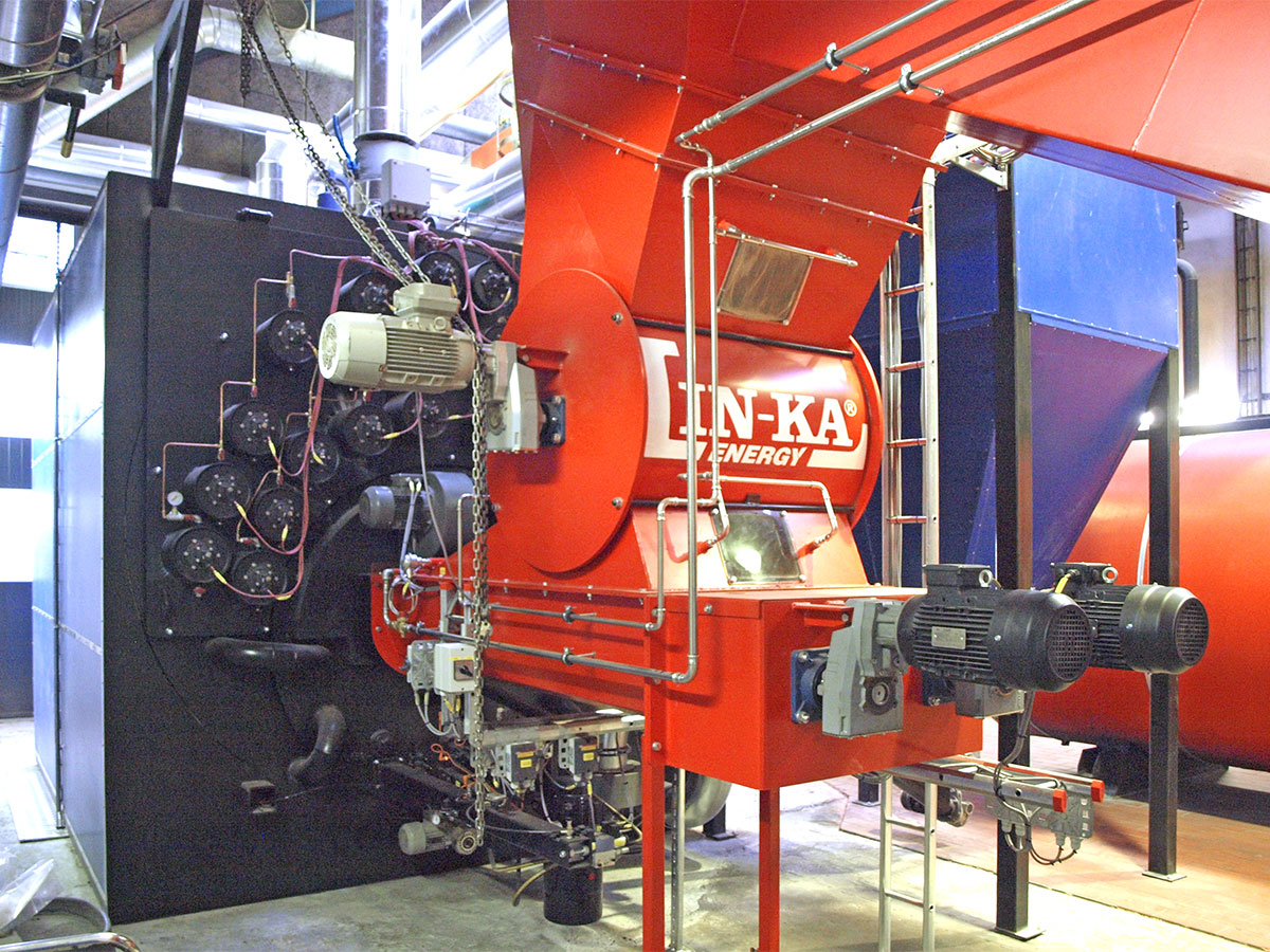
Biomass-fired multifuel system with a 2000 kW hot water boiler
Gjerlev Varmeværk A.m.b.a. was established in 1989 and shortly thereafter set up the first straw-fired boiler system – at that time, a preferable alternative to natural gas, which the area was already designated for. In 1990, the new straw plant was inaugurated.
In 2014, the heat plant added a 3,500 m² solar heating system as a supplement to the existing straw-fired boiler system, concurrently with the modernization of the original heat plant.
After careful consideration, in early 2018, Gjerlev Varmeværk A.m.b.a. applied to Randers Municipality for a loan guarantee to establish a new straw and wood chip plant to replace the existing straw plant, which was becoming obsolete.
The combined straw and wood chip boiler system provides the plant with more flexibility to switch between fuels, straw, and wood chips, offering complete freedom in fuel selection – and, not least, carbon-neutral energy and potentially lower heating bills for consumers in the long run.
Linka Energy A/S’ new 2000 kW multifuel biomass system was handed over to Gjerlev Varmeværk A.m.b.a. at the end of 2018.
The plant
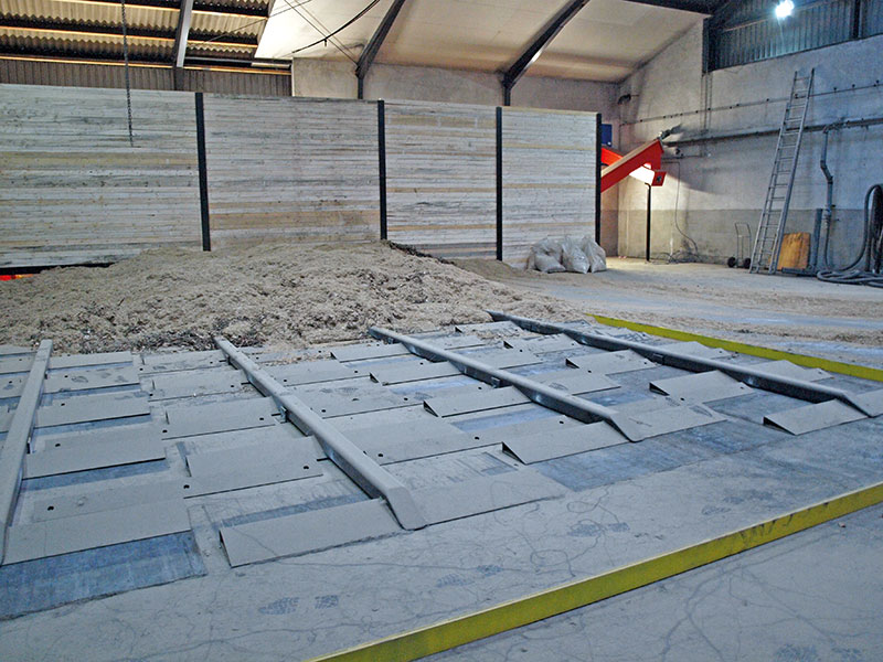
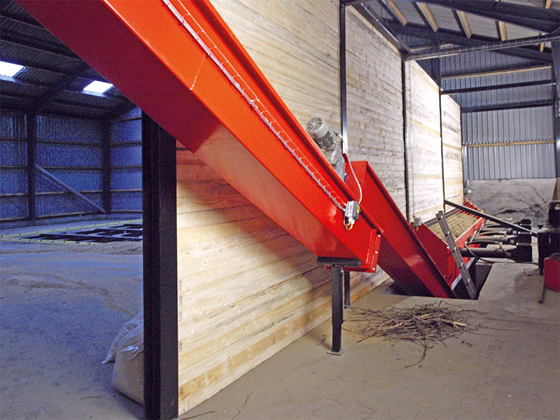
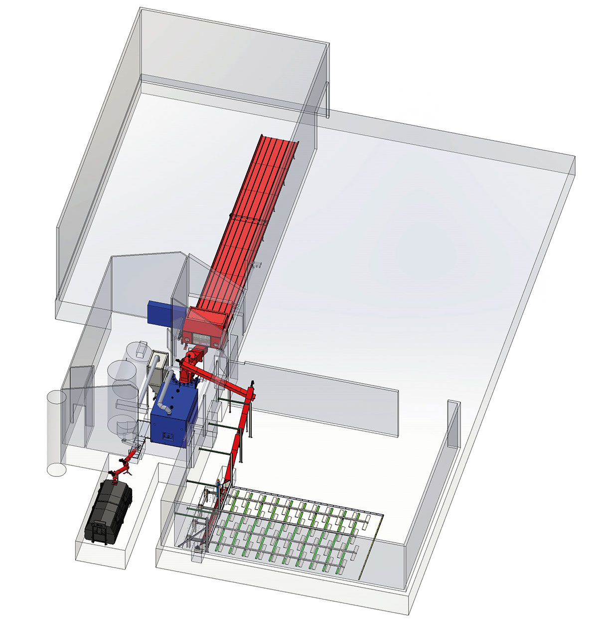
The boiler system consists of a 2000 kW Linka® H 2000 hot water boiler, capable of handling either straw or wood chips. This allows the boiler line with two feeding systems to operate independently of each other, ensuring a high level of security in the heat supply to the process, regardless of whether one of the feeding lines is taken out for service or similar reasons.
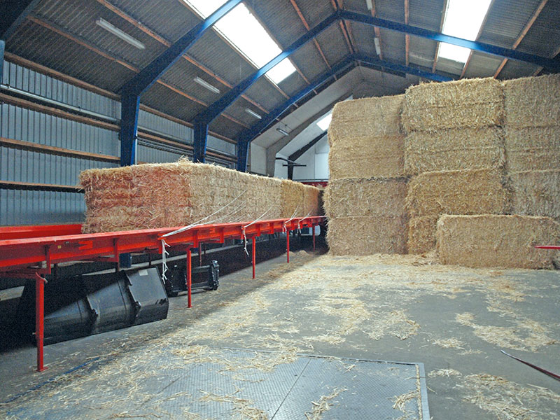
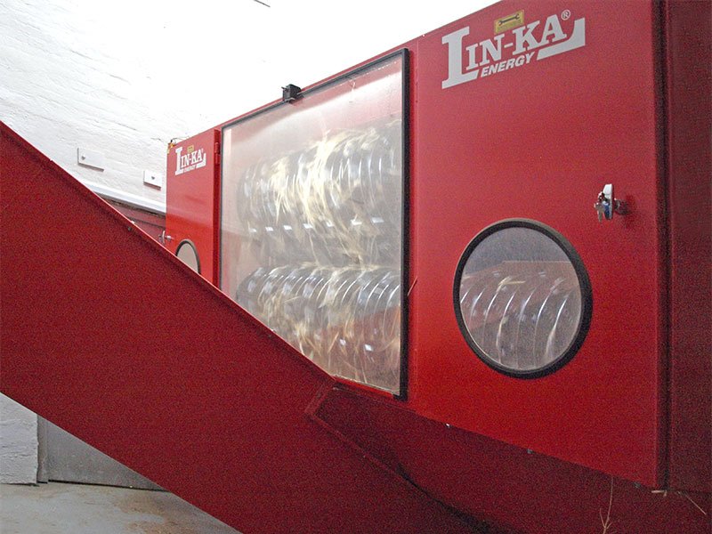
The straw handling system is equipped with a Linka TWIN straw table and a Linka TWIN shredder with rotating drums, controlled based on the boiler’s heat consumption. If the straw production is insufficient, the drum speed is increased. The shredded straw is transported to the straw auger, further to the cell lock and stoker auger (including fire extinguishing system), after which the straw is conveyed to the movable step grate located at the front of the boiler.
The wood chip handling system is delivered with 3 inclined augers and 6 cross augers.
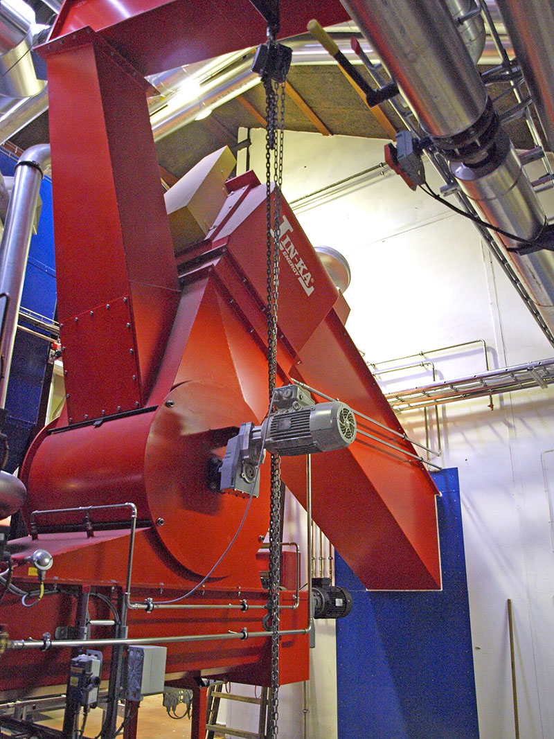
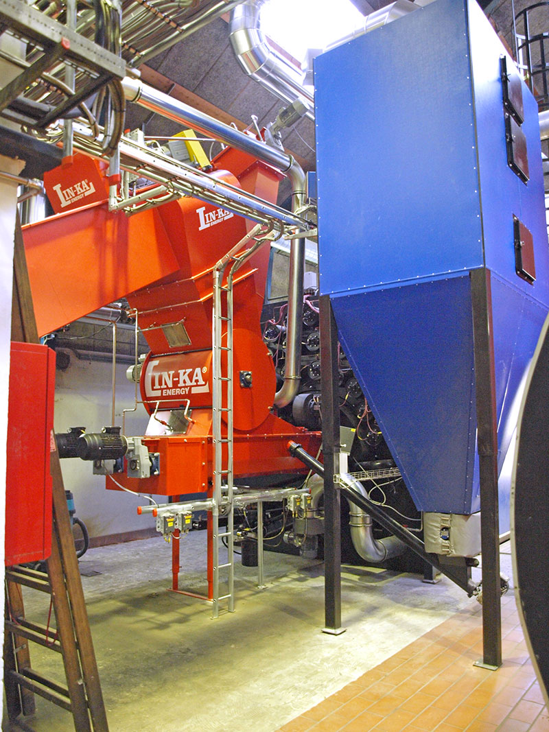
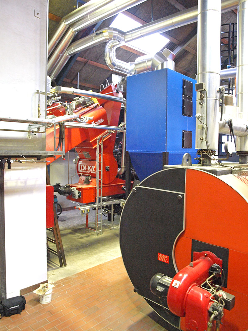
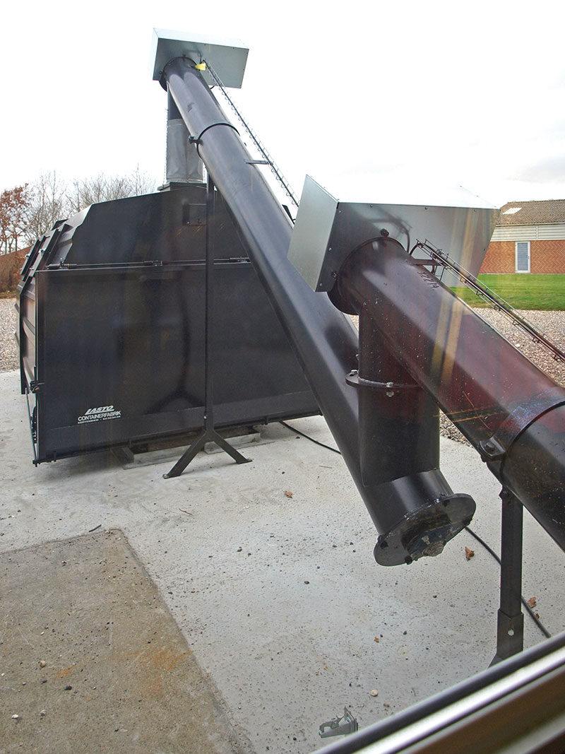
The hot water boiler, type Linka® H 2000, is designed for complete combustion and efficient utilization of radiant heat in the fire channel, while convective heat is maximized in the two subsequent flue gas tube sections. The step grate is constructed to prevent slag formation. Through Linka’s globally patented system, air from the firing end is drawn into the boiler in a counter current principle, efficiently burning the flue gas and yielding improved results in terms of efficiency and emission levels.
For automatic flue gas cleaning, several pressure tanks with shot valves are mounted on the front of the boiler. These valves release air through the boiler’s flue tubes, cleaning them of ash. This results in minimal manual cleaning time for the boiler’s flue tubes.
Additionally, a multicyclone is installed to clean the flue gas, thereby reducing dust emissions through the chimney. The ash is finally transported to a 20m³ ash container.
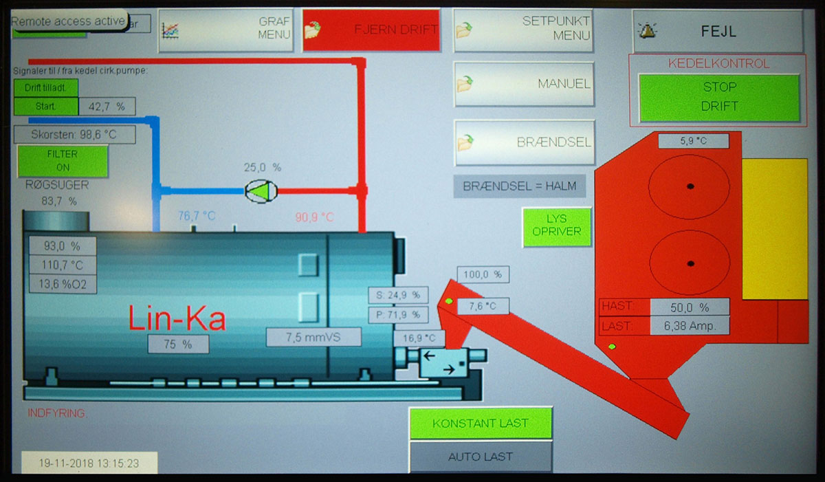
Control of the plant is done with a PLC control system that monitors the plant and sends out alarms via internet and SMS.
Specifications

Want to know more about this project?


Aneby AMAQ
References
Aneby AMAQ
Mobile heating ensures significant savings - for consumers and heating plant
During the summer of 2014 Linka installed a large, mobile heating plant for the Swedish municipality Aneby. The new plant has already resulted in significant savings on heating prices.
Aneby Municipality is located in the southern part of Sweden, 45 km from Jönköping. Aneby AMAQ (Miljø & Vatten AB) delivers heating for around 250 houses and a large industrial area. Before the new plant was installed, Aneby was Sweden’s most expensive area regarding heat prices. In only two years Aneby has advanced 85 spots on this list. Heating was previously delivered from a plant owned by a private company. Due to the agreement with the owner, AMAQ faced financial loss which affected the high heating costs.
After a visit at Mullsjö District Heating where Linka had previously installed a biomass plant, and with a plan to become self-sufficient, Aneby chose to invest in a new mobile heating plant.
Linka was chosen as the supplier due to our experience from delivering similar plants. We were also able to offer a reliable, flexible system for a competitive price. The contract between Aneby AMAQ and Linka was finalised in February 2014. Due to the expiration of their current supply agreement the new system needed to be operational in June, only six months later. A challenge, that Linka could meet.
The new plant was replacing a 6.3 MW boiler from the early 1980’s, and another 2.2 MW boiler along with an oil backup. An important factor for Aneby was flexibility in the construction of the plant. Linka was able to meet this demand.
By installing four 3,000 kW boilers instead of a large 12,000 KW, the supply is adjustable for the area’s changing weather. The installation of several smaller boilers ensures that the output can be regulated from only 300 kW up to 12,000 kW, when all boilers are operating on full loads.
While one of the boilers can supply the area with heat during warm months, it takes three boilers to keep the residents warm during the winter. This means that the fourth boiler is used as a backup for extraordinary cold weather.
The plant
Linka was a turnkey contractor on the mobile system which consists of four plant containers, two with wood pellet boilers and two with wood chips boilers. A service container with a small office, pumps and pressure system was also installed.
The wood chips boilers are fed from a large container. The chips are transported from a scraper unit through a distribution bin which distributes the fuel between both boilers. The pellets are stored in two large silos which feed the other boilers. The control system on the fully automated plant ensures a constant, optimal fuel feed to achieve the highest efficiency.
Ash from the boilers is automatically transported from the main containers to ash containers placed at the back. The plant only needs minimal supervision.
The combination of wood chips and pellets as fuel ensures a high flexibility. Aneby can change the primary fuel depending on pricing and supply, and achieve as low costs as possible along with a high supply security.
Specifications
Want to know more about this project?
Efficiency up to
91,9%
Based on efficiency tests of the two wood chip boilers, conducted by DGE Mark och Miljö AB in March 2015.
Dust particles
8%
The savings on heat for an average consumer, a villa with a yearly consumption of 20 MWh, is 150 EUR each year, or around 8 %.


"The collaboration with Linka has worked really well throughout the project. My experience is that we have had, and still have, a great mutual understanding."
Björn Stendal, VD
Aneby Miljö & Vatten AB

Tønder Fjernvarmeselskab
References
Tønder Fjernvarmeselskab
The new 3.75 MW biomass plant is connected to the existing natural gas-fired boilers and heat pumps
The new plant from Linka Energy will in the future cover approximately one-third of the heating demand in Tønder.
The price of biomass is highly competitive compared to the price of natural gas, and with a wood chip-fired plant of this size, sustainability is ensured. Therefore, the new wood chip plant contributes to securing both robust energy prices for consumers and a future-proof facility.
In addition to economic savings for the heating plant and consumers, the new wood chip plant will result in an annual reduction of approximately 4,100 tons of CO2 emissions.
The plant
The plant consists of a 3.75 MW Linka biomass boiler with flue gas condensation, developed and optimized in close collaboration with Linka Energy’s suppliers.
The wood chip firing is done via hydraulic pistons – a technology developed in collaboration with specialists from Linka Energy’s Swedish subsidiary, Jernforsen Energy. This, combined with Linka Energy’s globally patented combustion technology, ensures Tønder Fjernvarmeselskab (Tønder District Heating) a future-proof sustainable biomass-fired plant with high efficiency.
The fully automated, state-of-the-art heating plant is designed to ensure stable operation with a focus on user-friendliness and a good working environment for operating personnel. The manpower requirement is minimal, and the plant can even be monitored remotely, meaning that consumers always have access to heat.
Specifications
Want to know more about this project?
"As a district heating plant, we have a significant responsibility for the environment, and therefore, we have focused on a highly efficient and sustainable heating system powered by biomass fuel.”
Johnny Pedersen, CEO
Tønder District Heating


Stege Fjernvarme
References
Stege Fjernvarme A.m.b.a.
In 2020, Stege District Heating decided to replace their older straw-fired boiler with a new Linka boiler. In addition to the new boiler, the project also included an upgrade of the straw crane.
Stege District Heating supplies heat to approximately 1,300 consumers in Stege and the surrounding areas. Following the installation of the new boiler, the heating plant expects to expand its service area.
After the installation of the new Linka boiler, the operating staff can remotely control the system from home via PC. The entire system of Stege District Heating, including the solar panel system, is connected to remote control, allowing for technical support on short notice as well.

The plant
The boiler system is an 8.0 MW Linka GVB hot water boiler, ensuring maximum utilization of straw while maintaining flue gas temperatures at 115-120°C at full load.
The entire combustion process begins at the straw storage, where the straw crane deposits a bale into the safety box, then onto an 11.6-meter-long Linka tipping table (including straw table and inlet) and further to a Linka cutting machine that slices a portion off the bale. The straw slice is then fed into the combustion chamber using a hydraulic firing piston. The firing process is modulating, meaning variable piston speed/firing speed is controlled based on load and oxygen percentage.


The boiler is constructed with a combustion chamber followed by a reversal chamber. The flue gas then passes through a 3-pass economizer section with vertical flue pipes and shot valves at the top for cleaning the flue pipes. Shot valves are also installed in the reversal chamber at the bottom of the economizer for cleaning the reversal chamber.
The flue gas from the boiler passes through a multicyclone, LIN-KA type, and the new bag filter, Green Line 466-55-960 type. From here, the cleaned flue gas is directed to the new flue gas fan before being discharged through the existing chimney. The ash is transported to the existing wet ash storage.
The control of the system is managed through a PLC control system that monitors the plant and sends alarms via the internet and SMS. Additionally, it is possible to monitor the system via smartphones, tablets, and/or PCs. The new control system and electrical installations are integrated into the existing plant.


To comply with tightened emission requirements for new medium-sized combustion plants according to the Council of Europe Directive 2015/2193, implemented in Danish legislation through BEK 751 of 28/05/2018, an SNCR (Selective Non-Catalytic Reduction) system was also supplied for necessary compliance with NOx emission limits. The SNCR system is a “stand alone” system consisting of a tank for the reducing agent, a standardized pump module for softened water and the reducing agent, a process cabinet, injector(s), and control.
As part of the contract, the new boiler system was also to be delivered with complete additional firing for Stege District Heating’s existing wood pellet boiler system, and where possible, existing components were to be reused.

Specifications

Want to know more about this project?
Straw
2.044 kg/t
18% moisture
Efficiency
93,8 %
at 100% load


Lohals Varmeforsyning
References
Lohals Varmeforsyning
2.5 MW straw-fired boiler system with Linka® TWIN shredder system
Lohals Varmeforsyning was founded in 1992, and the facility itself was constructed in 1993. n 1994, a Linka 1.6 MW straw-fired boiler system was established for burning straw supplied by local farmers, along with an oil boiler as a backup with a capacity of 3 MW. Later, in 2011, the facility installed a combined wood chip and pellet boiler with a capacity of 2.0 MW to ensure a consistent supply of heat to Lohals town throughout the year.
When the straw boiler from 1992 reached the end of its “life”, Lohals Varmeforsyning and Linka Energy entered a new agreement in 2022 for the delivery of a complete 2.5 MW straw-fired system with a hot water boiler. This agreement also included the dismantling and removal of the old 1.6 MW straw-fired boiler, with the recycling of as many existing components as possible, such as the compressor, pressure maintenance system, bag filter, chimney, and ash container.


The plant


Product specifications
Want to know more about this project?
Efficiency
92 %
at 100% load
Straw
Approx. 640 kg/h
18% moisture

Toftlund District Heating
References
Toftlund District Heating
3.2 MW biomass boiler system for pellet firing
Toftlund District Heating issued a comprehensive project for the establishment of a complete wood pellet boiler, electric boiler, and accumulator tank. The present case concerns the wood pellet boiler contract, which Linka Energy bid on and won. As part of the installation of the new pellet boiler, the plant's existing gas boiler will be dismantled and disposed of.
The requirement for the new wood pellet boiler from Toftlund District Heating was to supply the existing absorption heat pump with hot water at 150°C. If the absorption heat pump is wholly or partially out of operation, up to 3,000 kW from the new wood pellet boiler should be able to transfer from the hot water circuit to the district heating circuit at a temperature of 98°C +/-1°C via a new heat exchanger dimensioned for 'the worst possible operational scenario’.
The plant
The boiler system, a 3.0 MW Linka H multifuel boiler, is configured for burning wood pellets but can also utilize other fuels such as straw pellets, wood chips, and sunflower seeds/pellets, thanks to its specially designed stoker with two parallel augers. The unique design of the H-boiler with a cylindrical combustion chamber, coupled with Linka's patented combustion technology, ensures the maximum utilization of the fuel.
An economizer has also been installed, serving as a flue gas cooler that transfers energy from the hot flue gas to a cooler medium - in this case, water - which can then be used for preheating or heating. This increases the plant's efficiency since more energy is extracted from the same amount of fuel. The economizer is connected to the flue gas system immediately after the boiler and before the flue gas cyclone.
When heat is “demanded” from the boiler, the firing procedure is initiated: the stoker auger starts and retrieves the required amount of fuel, depending on the heat demand, from the new steel pellet silo via the silo auger and delivers it to the fuel gate, from where it is introduced into the movable step grate inside the boiler.
Inside the boiler's combustion chamber, there is a movable grating to minimize slag formation, and the counterflow combustion system is Linka's patented global system. The flue gas from the boiler passes through an economizer, a multi-cyclone, and a bag filter, which purifies the flue gas, significantly reducing dust emissions before it is released through the existing chimney.
The control of the system is managed through a PLC control system that monitors the plant and sends alarms via the internet and SMS. Additionally, it is possible to monitor the system via smartphones, tablets, and/or PCs.
Specifications
Want to know more about this project?
Pellet consumption
675 kg per hour
at a moisture percentage of 8%
Efficiency
92,8 %
including economizer


Follo Fjernvarme
References
Follo Fjernvarme AS Boiler 4 - Drømtorp 2
Pellet boiler plant with a 2,000-kW hot water boiler
Previously, Drømtorp Næringsområde and Ski Idrettspark were part of what was called a "district heating island" that was not connected to the rest of the district heating network in Ski. Follo Fjernvarme AS therefore established a new energy center on Teglvej in Drømtorp, which now connects the district heating network from Glynitveien to Finstad. In 2021, Linka Energy A/S provided an additional boiler for the energy center, based on wood pellet combustion; thus, providing Follo Fjernvarme's customers with a stable, competitively priced, CO2-neutral energy supply.
The plant
The boiler plant, a 2,000 kW Linka® H hot water boiler, is a cylindrical and efficient channel tube boiler in a 5-pass design with a smooth fire channel and water-cooled reversing chambers, which, together with Linka's patented combustion technology and the use of flue gas recirculation, ensures maximum fuel utilization. When heat is "requested" from the boiler, the firing procedure is initiated: the screw conveyor starts and retrieves the amount of fuel, depending on the heat demand, from one of the new pellet silos via the screw conveyor and delivers it to the fuel lock, from where it is introduced into the movable grate in the boiler through the stoker. Furthermore, a bag filter of type Teldust (Greenline) is installed, which cleans the flue gas and thereby reduces dust emissions before it is discharged into the existing chimney stack. The ash from both the boiler and the bag filter is eventually transported to the two ash containers. The plant is controlled via a PLC control system, which monitors the plant and sends out alarms via the internet and SMS. It is also possible to monitor the plant via smartphones, tablets, and/or PCs.
Specifications
Want to know more about this project?
Pellets
454 kg per ton
max. 10% moisture
Efficiency
92 %


Warning: unserialize() [function.unserialize]: Error at offset 0 of 0 bytes in /var/www/linkaenergy.com/public_html/wp-content/themes/uncode/partials/elements.php on line 2380

BIO ENERGY AS
Reference
BIO ENERGY AS
Containerized multi-boiler system with 600 kW pellet boiler and 560 kW bio-oil backup
Bio Energy is a supplier of forward-looking and environmentally friendly clean energy to their district heating customers. They primarily choose energy solutions with a long-term perspective, developed in a cost-effective manner through continuous innovation thinking with a focus on economy and technology.
The multi-fuel plant consists of a hot water wood pellet boiler with a special designed bio-oil backup boiler (for the wood pellet plant), integrated into Linka's 40-foot container module. It is delivered with a chimney, pellet silo with screw discharger, oil tank, and ash container.
With the new plant, Bio Energy's customers in Ytre Enebakk will receive a stable, competitively priced, CO2-neutral energy supply based on wood pellets.
The plant
The boiler plant, consisting of a 600 kW Linka H hot water wood pellet boiler integrated with a 560 kW special designed bio-oil backup boiler (for the wood pellet plant), is equipped with a movable grate. With Linka's patented combustion technology and the recirculation of flue gases, it ensures maximum utilization of the wood pellets.
The wood pellets are transported via a stoker auger from pellet silo to the boiler in a suitable fuel quantity depending on the heat demand. Bottom ash is conveyed outside the boiler via ash cross auger and then directly to the ash container. The flue gas is cleaned in a multicyclone, reducing dust emissions, and then released through the steel chimney. Finally, the ash is transported to the ash container.
The plant is controlled by a PLC control system, which monitors the system and sends alarms via the internet and SMS. Additionally, it is possible to monitor the plant using smartphones, tablets, and/or PCs.
Specifications
Want to know more about this project?
Linka H hot water pellet boiler
600
kW
Bio-oil backup boiler
560
kW
Control system
PLC
via internet and SMS


ENVAFORS A/S
References
ENVAFORS A/S
New 12.5 MW straw boiler plant connected in the existing building at the straw heating plant "Stop 39"
The new straw fired plant from Linka Energy will contribute to SK Forsyning's strategy - running towards 2025 - about a sustainable future with the use of others CO2-neutral energy sources other than gas.
As the price of straw is very competitive in relation to the price of natural gas and with a straw-fired plant of this size, sustainability is also ensured. Therefore, the new straw boiler plant helps to ensure consumers both robust energy prices and a future-proof plant.
In addition to financial savings for SK Forsyning and consumers, the new straw boiler plant will result in an annual reduction of CO2 emissions of approx. 20,000 tons.
The plant
The plant consist of a 12.5 MW Linka® straw boiler with our unique, patented combustion technology, where combustion of the flue gases occurs completely and the CO content is further reduced and the fuel is utilized to the maximum.
Firing of the straw is done via the Linka® TWIN straw shredder system – a highly and well-proven technology – also developed to achieve the highest possible efficiency.
Linka's straw boiler plant can burn different types of straw - and of course it is also possible to burn seed grass, rapeseed and similar.
A 12,5 MW Linka® straw boiler plant is fully automatic and state-of-the-art, dimensioned to run staff-free for 72 hours of operation and can also be monitored remotely, which means that consumers are always guaranteed access to heat.
Specifications
Want to know more about this project?
Reduction in CO2 emission
20.000
tones
Boiler size
12,5
MW
Operating time
72 hours
unstaffed


"As a district heating plant, we have a great responsibility for the environment, which is why we have focused on a highly efficient and sustainable heating system that is powered by biofuel."
Carsten Lunde, Energy manager
Envafors A/S

Rødbyhavn District Heating
References
Rødbyhavn District Heating
CO2-neutral heating since 1988
Since 2007 Linka has delivered two 5,500 kW boiler lines for the district heating plant at Lolland. The plant uses straw for heating.
Rodbyhavn District Heating supplies the consumers in Rodbyhavn on Lolland, in the southern part of Denmark. The heating plant was established in 1988 with a 4,000 kW straw boiler. Two years later the plant was expanded with a 3,000 kW straw boiler. Both boilers were delivered by Linka.Both of these boilers were supplied by Linka.
In 2007 Linka was tasked with replacing the oldest boiler with a new 5,500 kW straw boiler, to accommodate the area’s increased heating demand. Linka delivered a complete boiler line from storage to ash system.
When the other boiler needed replacing in 2011 Linka was once again chosen as the supplier. This makes Linka the supplier for all boiler lines since the heating plant was established.
Today Rodbyhavn District Heating supplies 665 consumers in the area and they produce up to 38,000 MWh per year.
The plant
Both boiler lines consist of a 5,500 kW GVB boiler designed for straw combustion. The installed crane picks up a straw bale in the storage and drops it in the safety box, also placed in the storage. The bale is hydraulically moved into the straw cutter and are here sliced before being transported into the boiler for combustion.
An ash system is installed on both boilers, where the ash is automatically transported from the boiler to an ash container. The boiler lines are also equipped with a flue gas system with cyclone, filter and chimney.
Specifications
Want to know more about this project?
CO koncentration
351
mg/Nm3
CO emission from the plant is well below the limit value of 625 mg/Nm3.
Dust particles
<0,7
mg/Nm3
There is very little dust from the plant, compared to the limit of 40 mg/Nm3.
